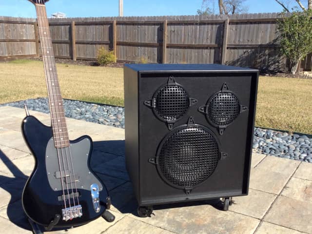
Ambassador Bass Guitar Speaker
Plans and Construction Guide
by Kevin Wilson
ver 1.1
Index
Overview
The "Ambassador" is a 200 Watt ported speaker with one 12" woofer and one 6" midrange driver intended for a 4 string bass guitar.
This page will provide specifications, design objectives, and details of the construction process.
Specifications
- Nominal Impedance: 8 ohms
- Frequency Response: 30 Hz – 5 kHz
- Power Rating: 200 Watts
- Dimensions: W = 21", H = 23.5" D = 19"
- Weight: approx 50 lbs
Parts List (partial)
- Celestion Pulse12
- Eminence Alpha-6CBMRA
- 400 Hz low pass crossover [6mH, 24uF]
- 800 Hz high pass crossover [3mH, 12uF]
- Port, 4" diameter x 4.5" length [Parts Express #299-2368]
- Plywood (1/2" and 3/4")
- L-pad (optional)
- 12" speaker grill [Parts Express #262-864]
- 6" speaker grill [Parts Express #260-371]
- Grill clamps [Parts Express #262-360]
- Neutrik NL4MP speakON connector [Parts Express #092-052]
- Terminal cup connector 2-15/16" [Parts Express #260-283]
- 1/2" acoustic sound damping foam pads [#260-520]
- Terminal Strip [Parts Express #090-870]
- Misc hardware (handles, screws, corner protectors, rubber feet, wire, paint, etc.)
Costs (partial)
| Cost | Item |
|---|---|
| $80 | Celestion Pulse12 |
| $65 | Eminence Alpha-6CBMRA |
| $50 | Crossover components |
| $5 | Port |
| $10 | Speakon / terminal cup connectors |
| $20 | Acoustic sound damping foam |
| $80 | Plywood |
| $20 | Paint |
| $80 | Misc hardware (wire, terminals strips, handles, etc.) |
| $20 | L-pad (optional) |
| $400 | TOTAL |
Design Overview
The Ambassador speaker is intended for someone who would like to save some money by constructing the speaker themselves and can accept a level of performance that may not be up to the level of a high quality commercially produced speaker. Primary design goals for the Ambassador were excellent sound fidelity, low cost, and an enclosure that's fairly simple to build and very sturdy.
Hoffman's Iron Law of Speaker Design states that we may choose two of the following - but never all three:
- Bass extension
- Efficiency
- Small enclosures
Restated: With a given amount of power you can be low, you can be loud, or you can be small. Pick two. I prioritized low and loud while designing the Ambassador speaker, which resulted in a larger enclosure.
Limitations - I want to be candid, I'm not an experienced speaker designer. I don't have access to measurment equipment (except a pink noise generator and RTA) or an acoustically proper testing room. I'm on a limited budget. Basically, I must rely on my ears and some luck during the design process. Please keep your expectation aligned with my circumstances. Having said that, I think I have a good ear for what sounds good, and I'm happy with the performance of the Ambassidor speaker.
WinISD was used to calculate the optimum enclosure volume, port dimensions, etc. The project file is available here: ambassador_ver01.wpr
Boxnotes was used to verify enclosure volume and identify problematic resonances.
Standing waves may develop around 620 Hz, 700 Hz and 850 Hz. Minor standing waves may develop around 320 Hz, 350 Hz and 440 Hz which corrospond to half wave frequency lengths. There's also quarter wave frequencies around 170 Hz and 210 Hz.
Sketchup was used to model the speaker. The project file is available here: ambassador_ver01.skp
A ported design was chosen because the Pulse12 driver is better suited for ported enclosures, and output efficiency was more important than fidelity. I used a tube port rather than a slot port to maintain a simple enclosure design. A round port with flared ends was used. WinISD calculated the port dimensions as 4" diameter and 2" length. Note: With a 2" port there seemed to be a 55Hz resonance peak and the low E note (41Hz) seemed a bit weak. I lenghtened the port to 4.5 inches which seemed to correct both issues.
A note about frequency response: The speaker was designed to accommodate a 4 sting bass guitar. The lowest frequency produced by the 4 string bass guitar is 41 Hz. Ideally the speaker’s frequency response should extend down to 41 Hz, however it should be noted that a significant amount of acoustic energy is present in the higher harmonic frequencies, therefore it is not necessarily required that the speaker's frequency response extent down to 41 Hz. It's my opinion that a -3 dB frequency of approximately 50 Hz and a -6 dB frequency of approximately 40 Hz will produce acceptable results - and will reduce costs and enclosure size. Any undesirable loss in lower frequency reproduction can likely be corrected with EQ. A 5 string bass produces lower frequencies and may require a speaker with a frequency response lower than this speaker design can provide.
An enclosure volume of 4.1 cubic feet was chosen primarily because it was the ideal values for a SC4 (Forth-Order Sub-Chebyshev) enclosure calculated by WinISD. The design produced a frequency response, port velocity, port length, group delay and other factors that were acceptable. Also, the design made efficient use of three sheets of plywood and a 19" rack case fits on top of the speaker. The empty enclosure is about 4.3 cubic feet. Driver volume is about 0.08 cubic feet. Port volume is about 0.02 cubic feet. The bracing is about 0.09 cubic feet. The effective internal volume of the enclosure is about 4.1 cubic feet.
The Eminence Alpha-6CBMRA has a sealed basket, so building a separate chamber to isolate it from the woofer was unnecessary.
The initial crossover design used 800 Hz second order 12 dB/octave Linkwitz-Riley high pass and low pass crossovers. However, the mids (around 800 to 1 kHz) seemed too pronounced. After inspecting the Pulse12 frequency response graph, I noticed a +6 dB peak around 2.5 kHz. This is past the 800 Hz crossover frequency, but I suspect it may have been preventing the crossover from producing a smooth 12 dB/octave slope. I increased the high pass crossover frequency to 1.2 kHz and was happier with the mid frequencies, but they still seemed to pronounced. I completly rebuilt the crossover using a 400 Hz low pass and 800 Hz high pass. This finally produced a fairly flat response that I'm happy with. The 800 Hz high pass Linkwitz-Riley crossover consists of a 12 uF cap and a 3 mH inductor. The 400 Hz low pass uses two 12 uF caps in parallel to produce 24 uF and a 6 mH inductor. In the future I may try a 4th order Linkwitz-Riley crossover. I may also add a 2 ohm resistor in series with the Alpha 6 to protect the amp it the Alpha 6 shorts.
The calculated frequency response curve is flat, with a slow roll-off beginning at about 130 Hz. The -3 dB frequency is 41 Hz and -6 dB is 35 Hz.
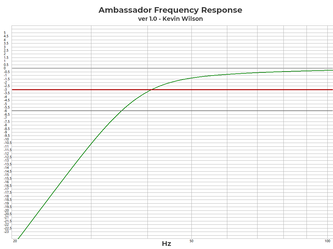
Frequency response (click to enlarge)
Maximum group delay is 17 mS at 35 Hz and drops to 9 mS at 50 Hz. It’s generally recommended to keep group delay under 20 - 25 mS. I have not heard port noise from the Ambassador speaker.
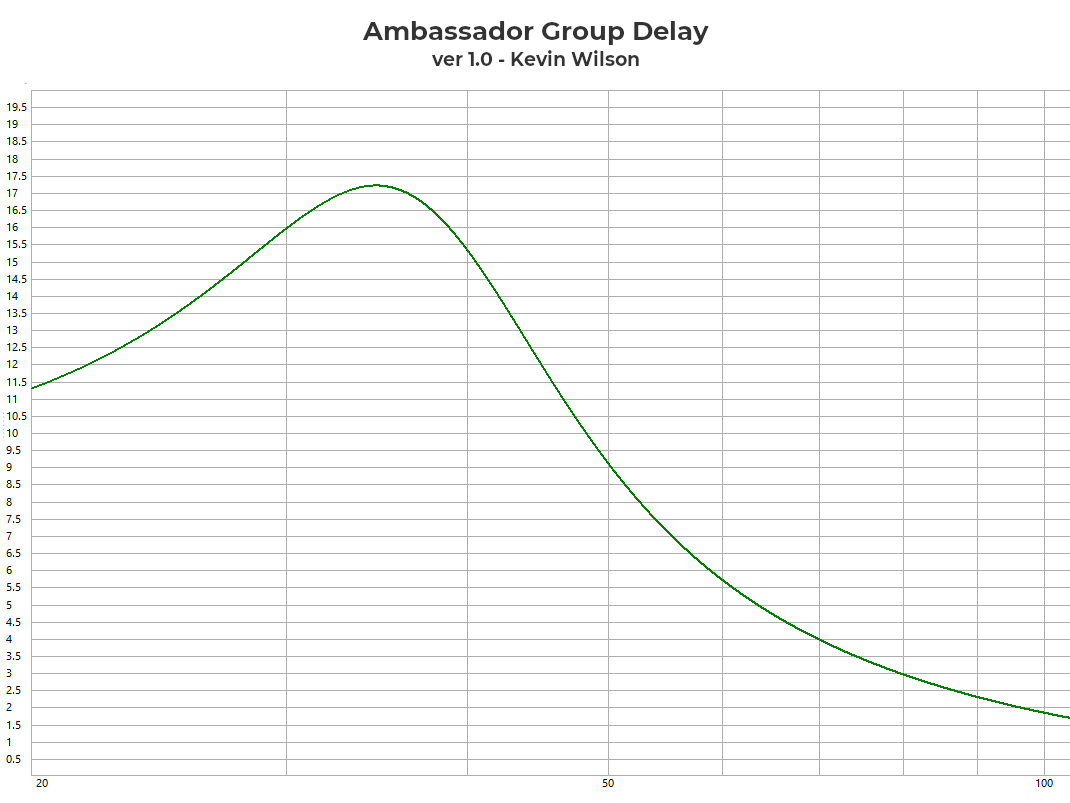
Group delay (click to enlarge)
Cone excursion can become a problem under 35 Hz, but using standard tunings and / or a high pass filter should prevent that issue.
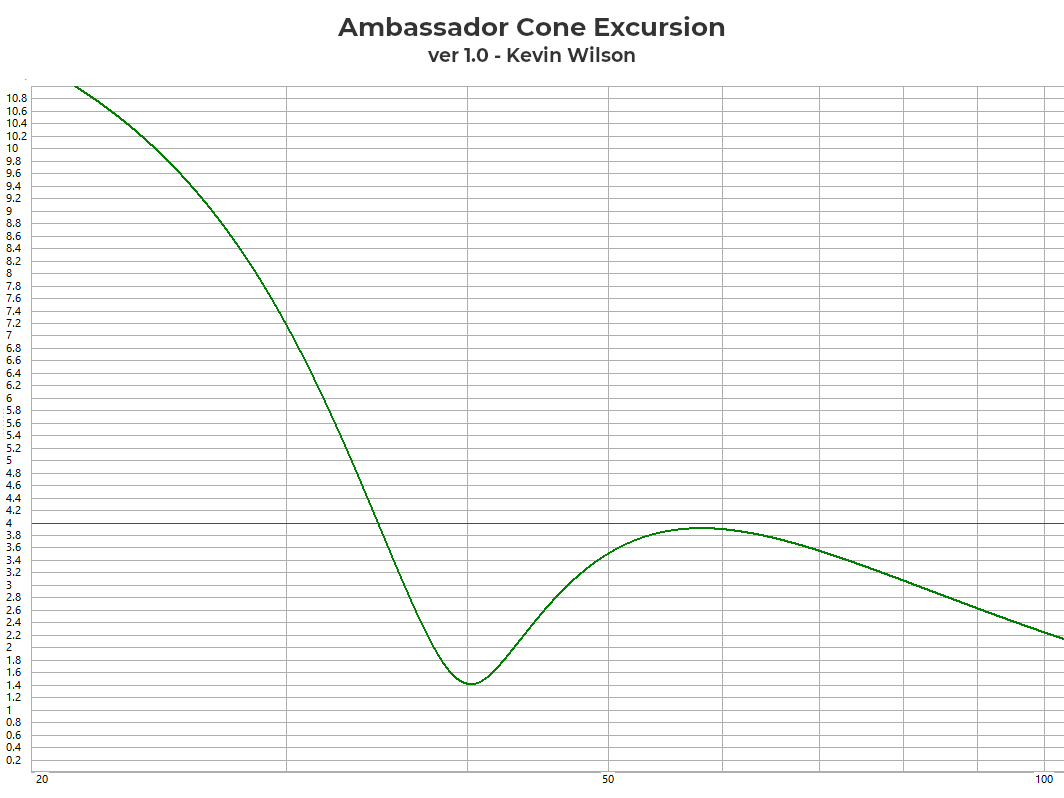
Cone excursion (click to enlarge)
Maximum port velocity is 19 m/s at 35 Hz. It’s generally recommended to keep port velocity under 20 – 25 m/s in relatively quiet environments.
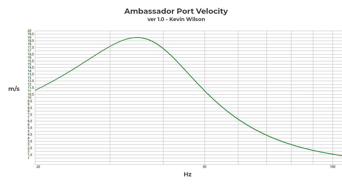
Port velocity (click to enlarge)
Construction Process Overview
Constructing the speaker begins with the plywood panels. First they'll need to be cut to size. Dadoes and rabbets will be routed to create solid joints. Circles for the drivers will be cut. (Instructions for making a circle jig are provided below.) The enclosure is partially assembled with internal bracing. Sound dampening pads are installed. The terminal block and crossovers are installed. The enclosure assembly is completed. The corners are rounded and the exterior is finished. Handles and casters are installed. All the wiring is connected. The drivers and the port are installed. The grills are attached. Finally, it's time to rock!
A fairly well equipped woodworking shop will be required to successfully build the speaker. The builder will need to be competent and familiar with general woodworking skills and techniques. I won't cover woodworking techniques or give detailed construction instruction in this guide. Constructing this speaker would not be a good first project for the new woodworker. Always wear eye and hearing protection. You'll want to ruin your hearing with a bad ass bass rig - not a table saw.
Panels
Enclosure:

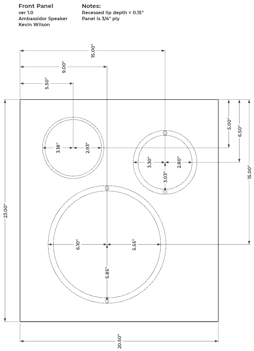
Front panel:
Rear panel:
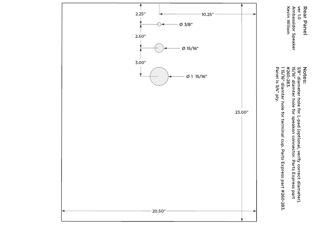
Rear routing:

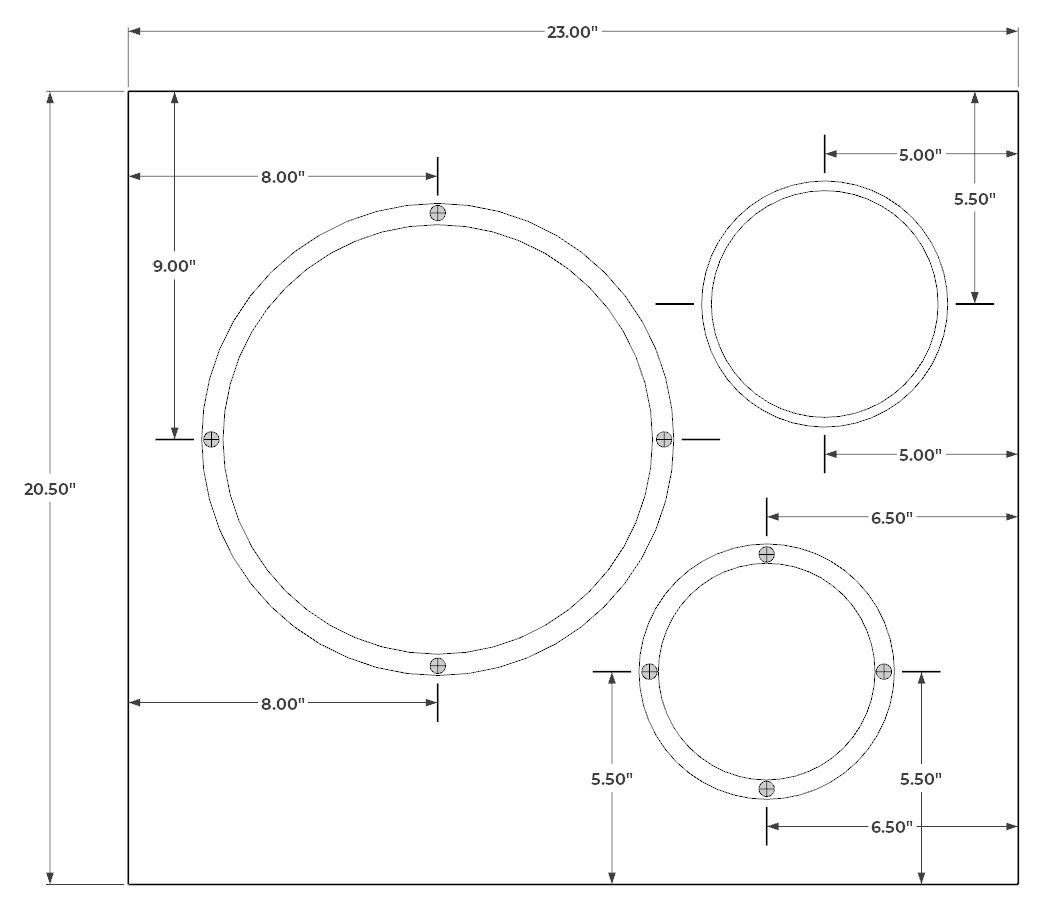
The design uses three sheets of 2'x4' plywood with minimal waste. The top, bottom and sides of the enclosure are 1/2" plywood. The front baffle and back panel are 3/4" plywood.
Panel Dimensions:
| Panel | L x W |
|---|---|
| Top, Bottom | 19" x 21" |
| Sides | 19" x 23" |
| Front / Back | 20.5" x 23" |
The remaining plywood cut-offs can be used for internal bracing and circle jigs. (Bracing layout cuts are only an example.)
The builder should be aware that actual plywood thickness may differ from the specified thickness. Plywood is typically about 1/32" thinner than it’s specified value. Router bits are available to accommodate the reduced thickness, for example: Yonico 14323. However, the actual thickness of MDF is generally the same as the specified thickness. Also, do not expect any sides to be straight or parallel. often the corners will not be square. It’s also common for the length and width of the sheets to be inaccurate by about 1/8", sometimes more. The edges of plywood are usually damaged and of poor quality. I strongly recommend that you first trim a small amount off each side of the sheet to improve the surface of the factory edge. Check each corner for square. There are several available methods to square the sheets, but that process is beyond the scope of this guide.
Route dadoes and rabbets in the top, bottom and side panels to accept the front and back panels. When routing the dadoes and rabbets remember the plywood thickness will be slightly less than the specified dimension. If you route a 0.75" dado then the 0.75" thick panel will be loose in the dado. The dado positioning needs to be accurate so the front and back panels will fit properly into the top, bottom and side panels. Avoid moving the router fence between cuts because it will be nearly impossible to reposition it in exactly the previous location. The dadoes should be routed into all the panels at the same time so there is no need to reset the router fence. Route the rabbets on the top and bottom panels. The width of the rabbets were the same as the width of the side panels. The depth of the rabbets should be 1 hair (0.001") deeper than the dadoes to prevent the dadoes from being visible on the sides of the enclosure. Finally, the front and back panels can be cut. The enclosure should be temporarily dry fit to verify proper fit. Some sanding may be required for a good fit.

Dadoes and rabbets (click to enlarge)
Holes were cut in the front and back panels using a router and a circle jig. The drivers should be recessed 0.2" to accommodate the height of the grill clips, although a recess is not required.
Due to the difficulty of enlarging holes and recesses after they are routed, it's much better to cut the holes a little large than a little too small. I recommend over-sizing the cutout and recess diameters by about 0.1".
If you are cutting holes with a jigsaw or maybe a laser, then you can skip the following circle jig construction guide.
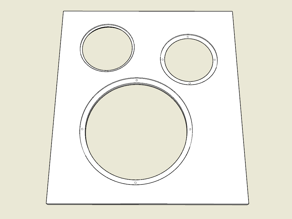
Front panel driver and port cutouts (click to enlarge)
Router Circle Jig
Circle jigs for the router can be purchased or made from scraps. You may follow this process to make a circle jig. You will need:
- A plunge router
- A piece of 1/2" or 3/4" plywood or MDF
- A few inches of 1/4" wood dowel
- A 1/4" drill bit or router bit
- Straight edge
- Calipers, ruler or tape measure

Router circle jig (click to enlarge)
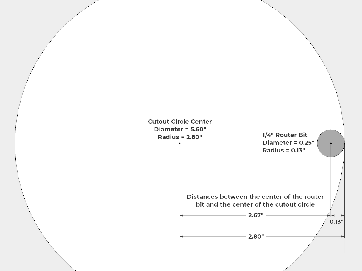
First determine the circle cutout radius for all the recesses and cutouts. The driver manufacturer should provide specification for the required dimensions. The dimensions I used are listen in the table below. I'll provide an example for this guide using the Alpha 6 cutout diameter of 5.6" that will be routed with a 1/4" diameter bit.
Next determine the distances between the center of the router bit and the center of the cutout circle. The distance can be found by subtracting the router bit radius (not diameter) from the cutout radius. For example:
Cutout diameter = 5.6"
Cutout radius = 5.6" / 2 = 2.8"
Bit diameter = 0.25"
Bit radius = 0.25" / 2 = 0.13"
Subtract the router bit radius from the cutout radius:
2.8" - 0.13" = 2.67"
Add 0.1" to the result to ensure the recess and cutout are large enough.
2.67" + 0.1" = 2.77"
The distances between the center of the router bit and the center of the cutout circle is 2.77"
This calculator will perform the calculations for you:
Drawing not to scale (click to enlarge)
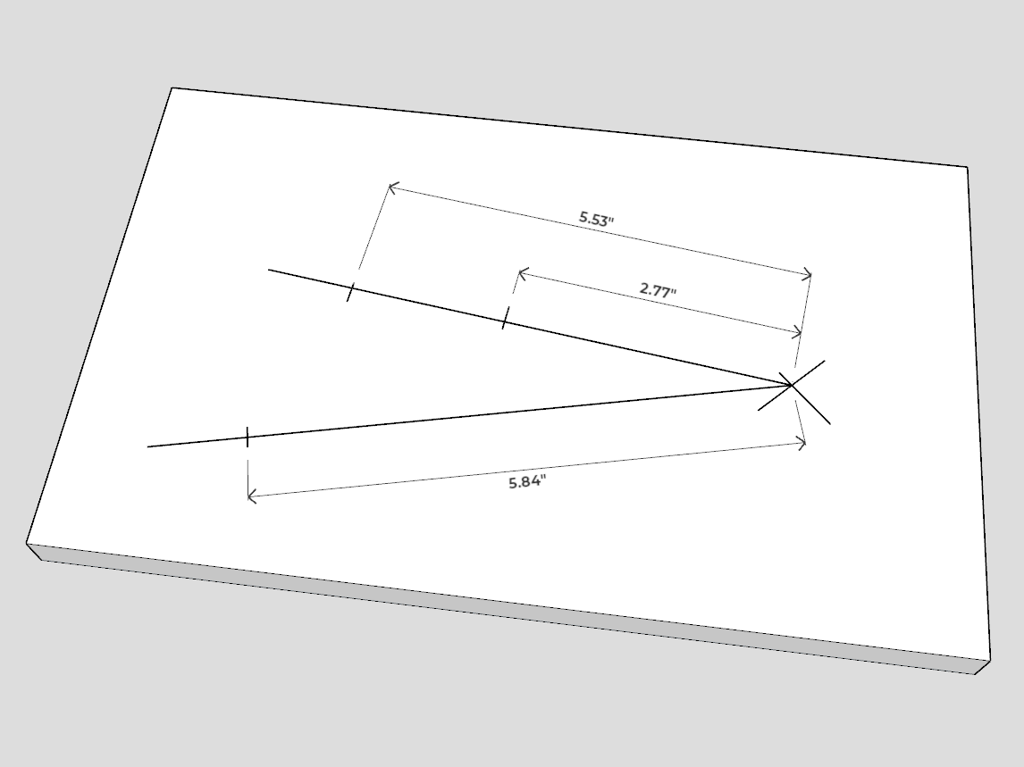
Based on my available bits I used the following specifications:
| Circle | Recess Or Cutout | Recess Or Cutout Diameter | Recess Or Cutout Radius | Bit Diameter | Bit Radius | Center To Center Distance | Distance + 0.1" Wiggle Room |
|---|---|---|---|---|---|---|---|
| Pulse 12 | Recess | 12.2" | 6.1" | 0.72" | 0.36" | 5.74" | 5.84" |
| Pulse 12 | Cutout | 11.1" | 5.55" | 0.25" | 0.13" | 5.43" | 5.53" |
| Alpha 6 | Recess | 6.6" | 3.3" | 0.72" | 0.36" | 2.94" | 3.04" |
| Alpha 6 | Cutout | 5.6" | 2.8" | 0.25" | 0.13" | 2.67" | 2.77" |
| Port | Recess | 6.36" | 3.18" | 0.72" | 0.36" | 2.82" | 2.92" |
| Port | Cutout | 5.86" | 2.93" | 0.25" | 0.13" | 2.81" | 2.91" |
| Terminal Cup | Cutout | 1.94" | 0.97" | 0.25" | 0.13" | 0.85" | 0.95" |
With the distances between the center of the router bit and the center of the cutout circle determined, we can begin marking the circle jig.
Mark an X on a piece of plywood or MDF. The X will be the center of the router bit. Leave enough space around the X to mount the router to the board.
Draw a straight line from the X to the far end of the jig.
Mark the line at the distances between the center of the router bit and the center of the cutout circle, for our example 2.67".
You may be routing and cutting several holes that are about the same size, which will result in several locations on the line that are very close together. In that case, simply draw an additional line extending out from the X to the side of the first line.
(click to enlarge)
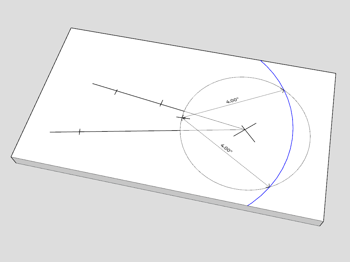
Now we will mark the router mounting hole location on the jig. The router must be accurately positioned so the bit will be centered on the previously marked "X". If you have excellent vision and some luck you can eyeball it, but I strongly recommend the following procedure.
First, determine the router mounting screw locations by measuring the distance between the screws. The mounting screws in my router are 4" apart. Using sketchup (free) I determined my mounting holes were in a circle with a diameter of 2.31". I think you can also use the formula:
Radius = Mounting hole distance / 1.73
Using my calipers set to 2.31" I scribed a circle around the X. I marked a spot on the circle as my first mounting hole location. I measured 4" from that first mounting hole to the intersection of the circle to mark the spot for the second mounting hole. Repeat for the third mounting hole. Recess the mounting holes so the jig can sit flush on the surface of the panel.
(click to enlarge)
Drill 1/4" holes into the jig in the locations you marked along the straight line(s). Drill holes for the router mounting screws. Recess the router mounting screws so the jig will sit flush on the surface of the panel. Drill 1/4" holes in the center of the recess and / or cutout circles on the enclosure panels.
If using a spiral bit, you can mount the router to the jig and plunge cut the hole into the center of the X. Otherwise you should drill the hole before mounting the router.
Cut a short section of the 1/4" dowel and put it in the 1/4" hole in the center of the recess and / or cutout circle on the enclosure panel. If one of holes in the jig is under the router base, verify the dowel is not too long and preventing the router jig from sitting flush on the panel.
Simply lower the jig onto the dowel in the panel. Of course, the dowel should go into the proper hole in the jig.
Proceed to route the recesses and cut the holes for the drivers, port and the rear speaker connectors. I recommend making several passes around the circle increasing the bit depth about 0.2" for each pass.

(click to enlarge)
Test the drivers and connectors for proper fit.
For convenience, the driver mounting holes can be located on the front panel before assembling the enclosure. Use the front panel dimensions to locate the midpoint of the drivers. Draw marks around the cutouts at the midpoint. Use the marks to align the drivers and locate the mounting holes. Install T-nuts if necessary.
Driver mounting hole locations (click to enlarge)
Bracing
Next the internal bracing can be installed. The primary purpose of the bracing is:
- To provide structural integrity against racking forces.
- Stiffening the panels to reduce vibration and flex.
- To aid in panel assembly.
Bracing the panels diagonally will resist racking forces. There are several bracing options available. Triangular pieces placed in the corners, boards attaching adjacent panels, etc.
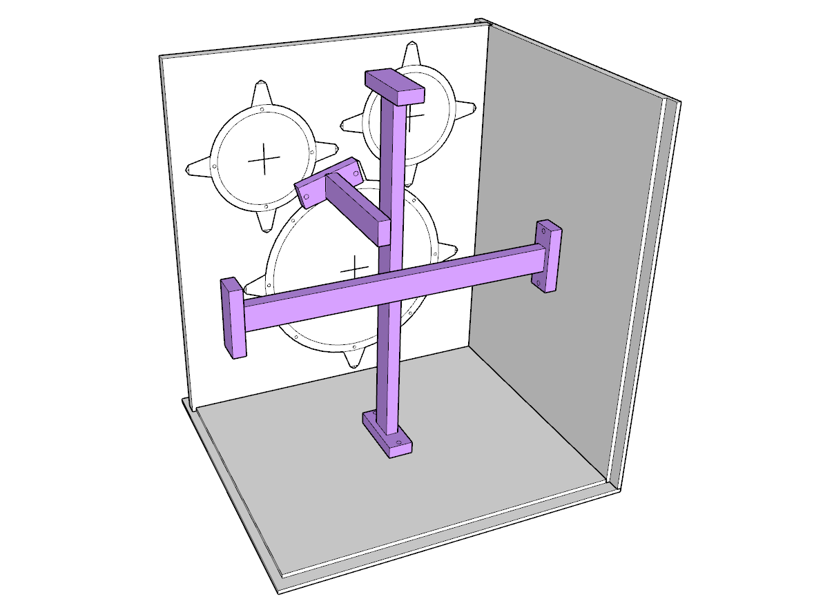
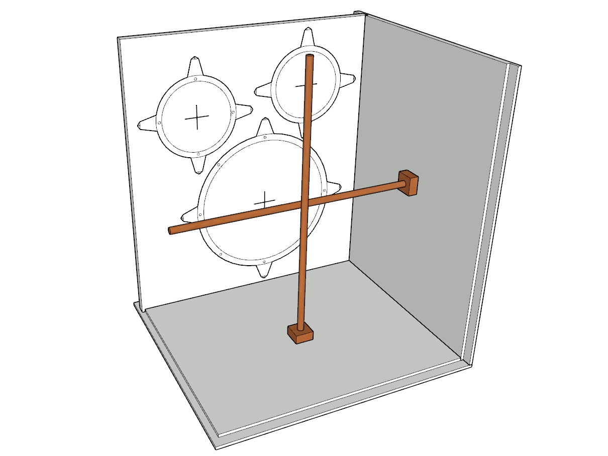
Most of the panel flex occurs at the center of the panels, so bracing the center will be the most effective method to reduce flex. Using braces to connect opposite sides of the enclosure is a good option because it braces two panels with a single brace.
Simple bracing stiffens panels (click to enlarge)
Boards can be placed along the edges of the panels before assembly to give the panels a mating surface. This is most useful when using simple butt joints. It's probably unnecessary with routed joints. Unfortunately, these braces will not resist racking or panel flex so they should be supplemented with other bracing options.
Of course, there are many other effective options available, but exploring all the options is beyond the scope of this guide. This is a good opportunity to be creative!
Corner bracing resists racking (click to enlarge)
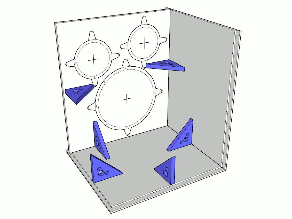
My bracing consists of a combination of triangle corner braces and boards connecting opposite panels.
The triangular corner braces were made from ply scraps. They're approximately 5" on each side (7" hypotenuse), but the size varied depending the dimensions of the cut-offs. I drilled holes in them to reduce weight and volume, but admittedly it was mostly to make them look cool. They are practically impossible to clamp into place while gluing so I planned to screw them the panels. However, I found that the braces refused to sit flush while tightening the screws, so I simply pressed them into place by hand. They seemed to be well attached after the glue dried.
The bracing boards were 2"x1" poplar board (actual 1.5"x0.75"). Using a butt join to attach a board to a panel will not hold, so the bracing boards were glued and screwed to a small board. The small board was then glued and screwed to the panel. All the bracing boards were glued together in the center of the enclosure.
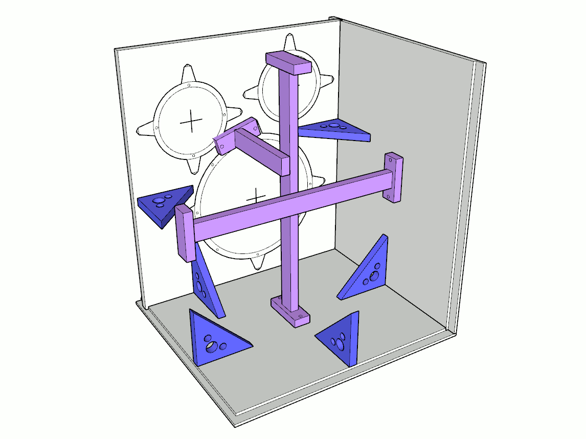
My bracing (click to enlarge)
The placement of the bracing is not critical, but insure the bracing does not interfere with the drivers, port, crossovers or the input jacks.
I considered using wood dowel rods for bracing. This bracing method would be very cheap and easy. The dowels would be glued into small blocks of board, then the boards glued to the panels. Similarly, I also considered threaded rod and T-nuts. I declined these methods because it would have been difficult to join the dowels or rods in the center of the enclosure. Although joining is not required, it helps reduce vibrations and bowing in the dowels or rods.
Dowel rod bracing (click to enlarge)
I considered this "star chamber" bracing design. It likely would have provided significant reductions in racking and flex, but the design was fairly complicated. The diagonal boards would have required difficult angled miter cuts on the ends.
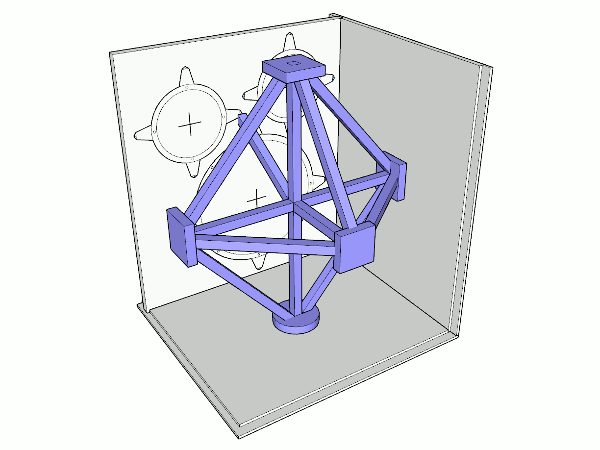
"Star chamber" bracing (click to enlarge)
I call this bracing design "the matrix". Although I believe it would have provided excellent bracing, ultimately I concluded the structure was excessively complex.
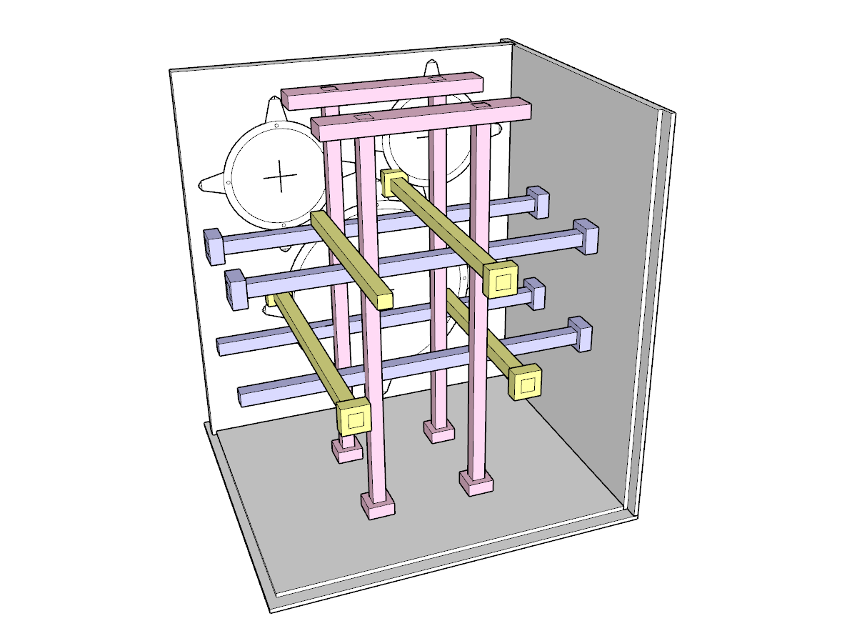
"The matrix" bracing (click to enlarge)
Assembly
The enclosure can now be glued and assembled. Assembly was not quite as straight forward as one would think. The internal bracing needed to be glued into place, but they could not be glued while the panels they attached to were in place (because there would be no way to get glue between the braces and the panels). Basically, I assembled the enclosure by first gluing the front brace to the front panel. Next I partially assembled the enclosure by gluing the bottom, front and one side panel together. Then I glued the bottom end of the vertical internal brace to the bottom panel and the front brace. Next I glued one end of the horizontal brace to the glued side panel and the vertical brace. Finally I completed assembly by gluing the remaining panels in place. I did not attach the rear panel to allow easy access to finish the interior surfaces, mount the crossover, install sound dampening pads and mount feet and handles.
I glued small pieces of boards or plywood scraps in the feet (or casters) and the handle mounting locations to give the mounting screws a better opportunity to hold. I wanted the enclosure to be balanced when it's picked up with the handle. I determined the center of mass by placing a 10lb weight on top of the enclosure just behind the front baffle to simulate the drivers. I placed a thin board under the enclosure and moved the board until the enclosure was balanced on the board. The center of mass was found to be 9" from the front edge of the enclosure. I glued the diagonal braces in place.
The rear panel will be installed after interior surface sealing / painting, but the attachment location for the rear brace cannot be sealed / painted (wood glue won't adhere). I temporarily put the back panel in place and marked the location where the rear brace and diagonal braces attach. Then I used masking tape to mask those area. I also masked the edges of the panel where it will be glued to the other panels. Also mask the locations where the rear brace will attach to the other braces.
A caulk or construction adhesive can be applied to the joints to ensure they are completely sealed, although this step is almost surely unnecessary, especially in a ported enclosure with routed and glued joints.
Interior Prep
At this point the interior surfaces of the enclosure can be sealed or painted. This step is likely unnecessary unless the enclosure will be exposed to frequent and extreme changes in humidity or if it remains in a humid environment for extended periods of time. Plywood is generally tolerant of humidity and moisture, but MDF can swell and break down over time. If a finish is applied, I recommend spray paint, shellac or wipe-on polyurethane. Spray paint is the easiest option. Polyurethane will require about 1 week for the smell to dissipate but it provides excellent protection against moisture. Shellac provides good protection, dries quickly and does not have a strong odor. Do not leave used rags in a pile as they may spontaneously ignite.
Acoustic sound dampening / absorption pads were applied to the back, one side and the top of the enclosure. One goal of acoustic treatment is to reduce sound waves reflecting between opposite walls. Insulating one side, in theory, is sufficient to reduce the reflections. I used standard foam insulation, but it should be noted that effectively absorbing bass frequencies requires several inches of relatively dense insulation. Unfortunately, the cost and effort to install proper insulation is probably not practical. Standard foam insulation (similar to what I used) will mostly absorb higher frequencies. It provides minimal benefit in a bass guitar speaker. However, if you wish to include proper acoustic insulation, I recommend Owens Corning 705 rigid fiberglass panels. The 705 panels are expensive and very difficult to find. The 703 panels are a suitable alternative. A total thickness of about 4" provides excellent bass frequency reduction, but due to space constraints a thinner layer should be used. I recommend 2 inches.
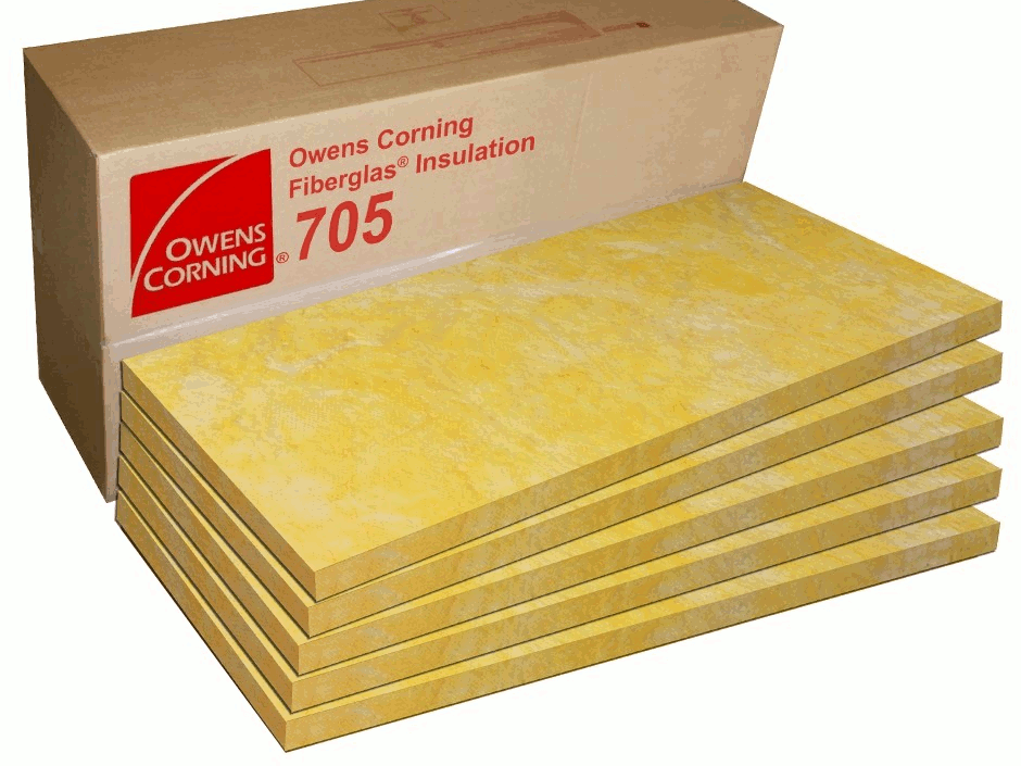
Rigid fiberglass panels (click to enlarge)
Wiring
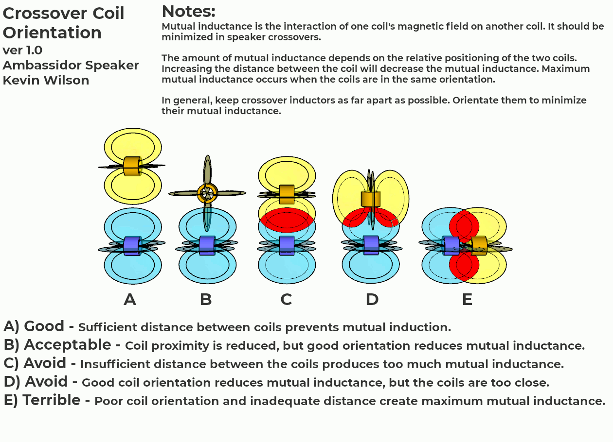
The crossover and terminal strip block can be assembled and installed on the floor or wall of the enclosure. Crossover inductors should be positioned to minimize coupling (cross talk). Ideally, the low pass crossover inductor core should be oriented vertically to minimize coupling with woofer voice coil.
Refer to the plans for more information about crossover coil orientation and a wiring schematic.

Wiring Schematic (click to enlarge)
Crossover Coil Orientation Details:
Finally, with all the interior work completed, the back panel can be glued in place.
Exterior Finishing
All the ply edges and joints were filled with wood filler. Edge banding is another option. The entire surface was sanded. If desired, the panel corners can be rounded over using a router. Some corner braces / protectors require rounded corners.
The enclosure can be finished with paint, stain, polyurethane, etc. If using polyurethane, I recommend using wipe-on poly. Apply a thin coat with a link free rag (old t-shirt). Let it dry in a dust free location for at least 12 hours. Sand it very gently with 600 - 1000 grit sandpaper. Repeat with as many coats as desired. At least 3 coats are recommended. Do not sand the final coat.
The strap handle and feet / casters were installed.
The wiring and the rear connectors were installed. The drivers and the port were mounted. The grills were installed.
Performance Evaluation
First impressions - the Ambassador speaker sounds pretty good! My two primary concerns were potentially insufficient high frequency response and imbalance between the two drivers. (The sensitivity of the Eminence Alpha-6CBMRA is 3.8 dB greater than the Pulse12.) Those concerns were apparently unwarranted. There seems to be no shortage of high frequency response and the driver balance seems to be fine.
The following EQ settings were used to get a typical modern tone with a strong fundamental, scooped mids and bright high frequencies. My signal chain was: guitar -> TC Electronic SpectraComp -> Behringer Ultracurve EQ -> Crown XLi 800 power amp -> Ambassador. The gain on the SpectraComp was increased to 20 dB so it acted as a preamp.
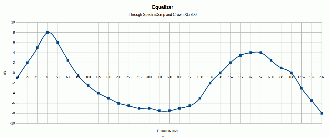
Equalizer Curve (click to enlarge)
Note: The Ambassador speaker, to my ears, sounds better than the frequency response test results. I can clearly hear a 40 Hz fundamental when hitting the open E string, although the frequency response graph shows a significant drop-off below 60 Hz. While running a 40 Hz sine wave through the speaker, the volume changed quite a bit as I walked around the room. I believe there were standing waves that developed and skewed the tests. Unfortunately, I have to way to correct the room acoustics. Also, I'm not sure the Fender Rumble amp that I'm using produces adequate low frequency. That amp was designed to run a crappy 10" driver that clearly did not produce much output below about 60 Hz. The amp's frequency response is not listed in the specifications. I did not run the drivers through any break in process. At the time of testing they have been used a couple hours at low volume. I'm unsure if their "newness" had any effect on the test results.
The frequency response was measured with a Behringer Ultracurve Pro DSP8024 and a Behringer ECM 8000 Omnidirectional Measurement Microphone. The Ultracurve was connected to a Fender Rumble 40 amp. The driver was removed from the Rumble amp and the speaker leads were connected to the Ambassador speaker. The amp tone controls were set to 12 o'clock position and the bright, contour and vintage controls were disabled. The microphone was placed 9 feet directly in front of the speaker at a height of 1 foot. The Ambassador was placed in my living room. It's a fairly large room with coffered ceilings and the usual complement of furniture. The kitchen is directly adjacent to the living room, separated by an island. Obviously, the room is not intended for acoustic measurements, however I suspect the acoustic properties were adequate for the tests. The pink noise generator in the Ultracurve was run through the amp and the Ambassador speaker while the RTA in the Ultracurve generated an EQ curve to correct any frequency deviations. Inverting the EQ curve results in the speaker's frequency response.
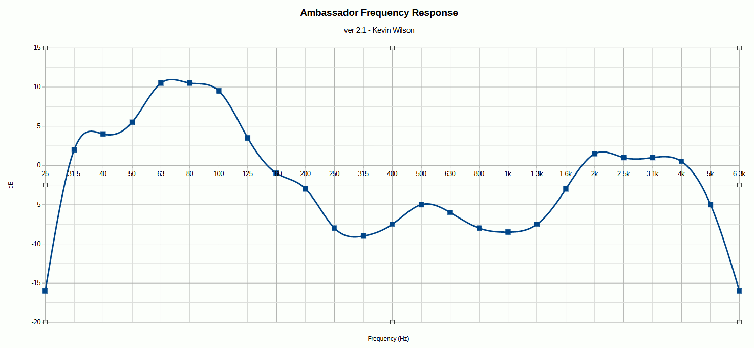
Measured Frequency Response (click to enlarge)
Phase
The Alpha6 midrange driver was out of phase, so the polarity of the leads had to be reversed. The phase was reversed due to the high pass crossover circuit.
Testing the phase was surprisingly difficult. First I tried a simple listening test by playing along with my stereo and switching the polarity. I could not detect any difference. Next I used my RTA to generate 2kHz - 5kHz sine waves through the driver and a stereo speaker. I measured the volume with my reference microphone. In theory, the volume level should be higher when the speakers were in phase due to lack of signal cancellation, however the results were inconsistent and inconclusive. I believe standing waves developed and ruined the test. Finally I measured the voltages across the input jacks and driver leads. In theory, there should be no voltage drop when the signals at the jack and the driver terminals are in phase. I used the free Falstad online circuit simulator (a great applet!) to model the Ambassador crossover and driver circuit and verify the theory. The circuit schematic file is here: falstad_ambassador.txt. The easiest method to test phase is to measure the AC voltage between the negative input jack and the positive terminal of the driver. If you measure 0 volts, then the driver is in phase.
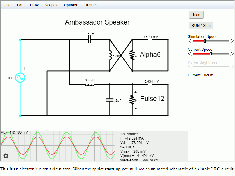
Falstad circuit simulator
What is phase? In technical terms, phase refers to the time relationship between two or more waveforms. In non-technical terms, imagine your band has two guitar players. One player starts playing a song then the second player starts a second later. It sounds all jacked up, right? The guitars are out of phase. One player is hitting an E power chord while the second is running through a D minor chord. They aren't working together and it sounds like crap. The same thing can happen with speakers.
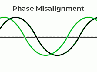
Phase Misalignment
Why is correct speaker phase important? When speakers are out of phase it reduces the quality of the sound. If they're just a little out of phase, then they will sound kind of dull and lifeless. If they get really out of phase, then the sound from one speaker can cancel out the sound from another speaker. Obviously this is something to be avoided.
There's audio processing equipment that can adjust signal phase and correct minor phase misalignment. Probably the most popular is the BBE Sonic Maximizer. Behringer makes the Sonic Ultramizer SU9920. These are intended to correct relatively small phase changes produced when your audio signal is passed through the inductor in your driver's voice coil.
If you accidentally switch your speaker or crossover + and - connections, then your signal will be completely out of phase. This will cause severe sound degradation due to signal cancellations. In this case the only solution is to find which connection is switched and correct it.
Fortunately, bass rigs don't have to worry as much about phase - although it can still be a problem. Multi-channel systems (stereo, 5.1, etc.) are at risk of phase misalignment because they have multiple speakers and every speaker must have the same phase. Bass rigs are usually mono, so that eliminates one potential cause of phase misalignment. Some bass speakers only have one speaker, so it's impossible to be out of phase with other drivers. A 2-way mono speaker like the Ambassador is generally immune to phase issues. Although it has two drivers, and they can be out of phase, it's usually not a big problem because the crossover splits up the input signal and sends different signals to each driver. I've switched the phase of both drivers in the Ambassador and it didn't seem to make any difference. There was a slight volume reduction in the frequencies around the crossover point (800 Hz), but it didn't seem to affect the overall speaker output. Having said that, when playing with a band it's still possible for the bass driver to be out of phase with other speakers (lead / rhythm guitar, keyboards, etc.) and cause issues.
Acknowledgments
I want to thank my awesome wife Cindy who paid for this project and puts up with me.
Thank you to Bruce Gardner, professor for most of my electronics classes and a really fun 1 credit hour class on speaker theory and design.
Thanks to my friend Mark Dauzat who helped me build my first speaker circa 2002.
This project was inspired by greenboy.